C1-83 Oscilloscope Manual

No part of this manual may be reproduced in any form or by any means. Agilent 1000 Series Oscilloscopes User’s Guide 13 Figures Figure 1. Power Switch 19.
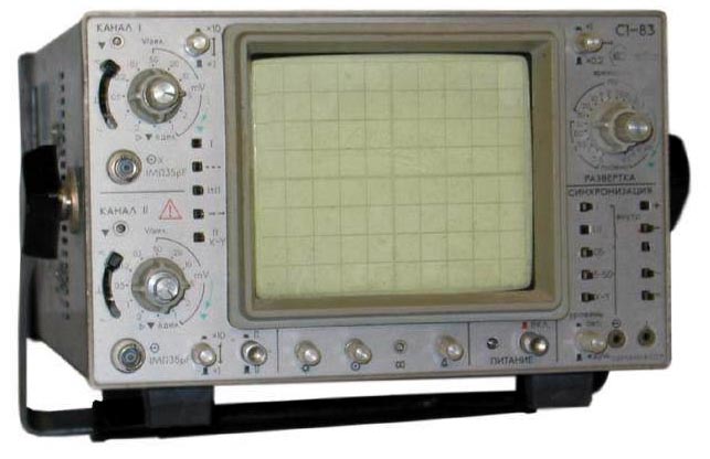
Hello everyone, I've just got hold of an old Russian S1-83 (C1-83) Oscilloscope that requires some work to become operational. I've never seen a power connector of this sort (see Images attached) before so I was thinking of replacing it with something more standard to save time and hassle. The back panel shows the power input requirement so I'm fairly sure its going to be fine. However the cabling used for it doesn't look thick enough for power (although its only 50 watts so maybe its fine). Has anyone seen this connector before or know if my plan is going to work? I'm very new to this sort of thing and this is my first oscilloscope so it would be nice to get it up and running. If you have any questions about the project feel free to ask.

Also if you want more photos or see something interesting let me know. Thanks, Will Next stage: I've tried to trace the two cables I believe to be active and neutral but haven't had any luck in finding where they terminate in order to distinguish the two.
I'd prefer not unscrew to much as I fear I might not be able to put it back together considering the little information available. I read that if the active and neutral are wired in reverse it can cause the chassis and/or other components to become live while the device is off. Therefore, I was wondering if it was possible to wire the device not knowing which wires are which and then testing to see whether the polarity is correct or not and then act accordingly. Or could this method damage the oscilloscope.
(Pardon my ignorance). I am not familiar with Russian earthing arrangements from that era. Were grounded outlets common in the era this scope was designed? I would just trace the circuit from the power connector. I would expect some combination of wires going directly to case, to a switch and/or fuse, and to primaries of transformers.
From this you should be able to infer the correct wiring. A wire going directly to the case is most likely ground and should have a high resistance to either of the other wires. The wire through the fuse/switch should ideally go to hot, and the wire going directly to the transformers to neutral, but the latter is not that critical (it would not surprise me if they originally used a non-polarized plug). If one of the primary sides of the transformers is directly connected to the case, than you may have a hot chassis (neutral connected to chassis). That would warrant some care.

Tektronix Oscilloscope Manual
But I would expect this scope to be way too modern for that. Test equipment (at least in Western countries) was usually more modern than consumer equipment in that regard.